High-pass filter frequency response
Having available the gain and phase shift equations for the high-pass filter:
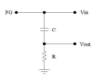
- Interchange R and C and repeat the steps outlined for the low-pass filter
to graph log G(f) vs. log(f) and φ(f) vs. log(f) for a high-pass filter.
Use either the Vout,Δt or the Lissajous method to determine G and φ for your well-chosen set of frequencies that should include f0.
- Compare the centre frequencies f0.
- Compare the filter gains and phase shifts at f0.
- How do the phase shifts of the two filters differ? Do the output signals lead or lag the input signals?
- Compare the roll-off rates. What is the order of these filters?
RCL band-pass filter
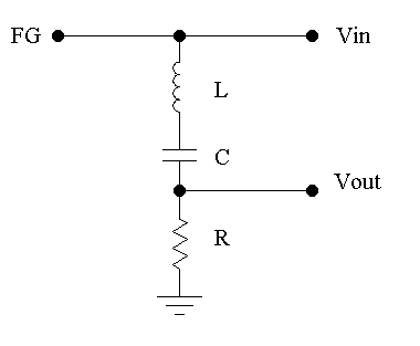
Adding an inductor L to an RC circuit produces a band-pass filter that passes frequencies within a certain range while attenuating frequencies outside that range.
- Setup your circuit as shown with an inductor L = 2.2mH, C = 0.01μF and R = 100Ω.
- Set the FG to 5Vpp sine wave.
- Sweep the frequency and note qualitatively the changes in gain and phase shift between the input and output signals. You do not need to tabulate G(f), φ(f).
- Note the frequency fbp where the G=Vout/Vin is a maximum.
- What is the phase shift φ between Vin and Vout at fbp?
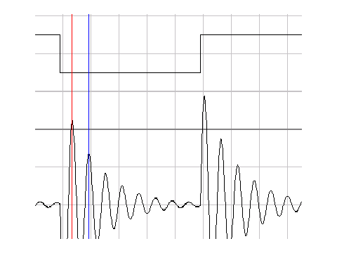
Driving the RCL circuit with a rapidly changing voltage such as a square wave will cause the circuit to undergo such damped oscillations, as shown. To view this effect:
- determine f0 for this filter, using measured RCL values;
- set the FG to output a 5Vpp square wave of about 0.1 f0;
- zoom into the waveform and measure the gain and time of two points on adjacent peaks of the ringing signal.
- Determine the ringing frequency f0;
the decay time constant is given by τ = (t1 - t2)/(ln V2 - ln V1)
- Use this equation to estimate τ
- Compare your results for f0 and τ with those predicted by the theory. Do the results agree within experimental error?
- Compare your f0 results with the previously estimated fbp.