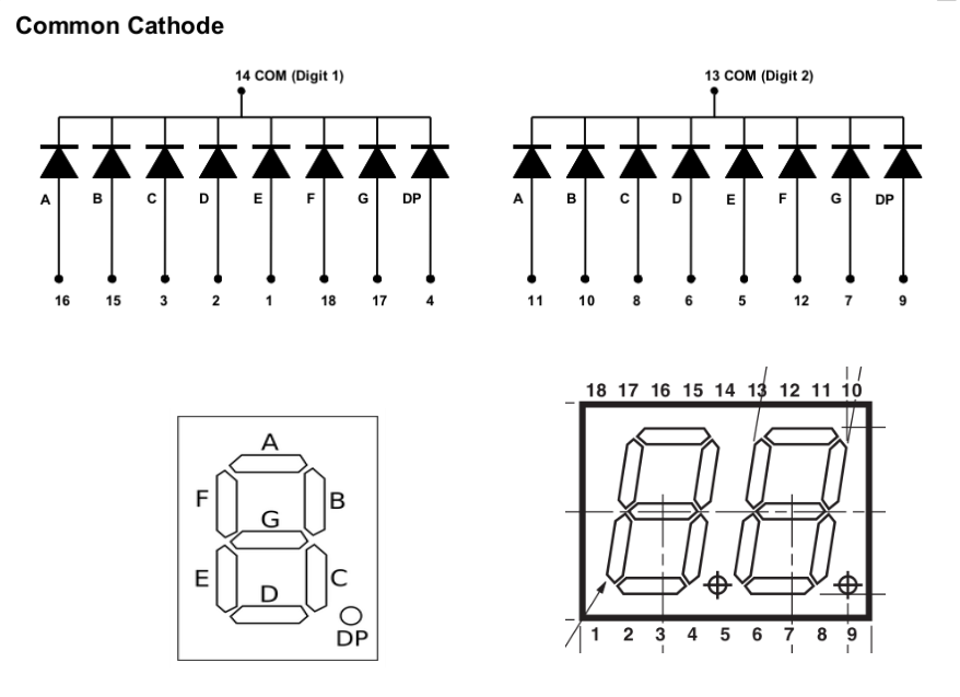
The 7-segment display
We will use PIC pins RA0 to RA7 to interface to the the a-g,dp segments. At the start of your programs, include the following code that will set PORTA pins RA0-RA7 to output ~0V or ~5V:
SetOut	Bank1		;select data direction register page
	clrf	TRISA	;set all PORTA pins to output
			;a voltage on RA0-RA7
	Bank0		;back to user memory page
To begin, flash the display segment 'a' as previously done with the LED connected to the PIC RC0 pin:
- Connect one end of a 470Ω resistor to the RA0 pin.
- Connect the other end to the Digit2 'a' segment, pin 11.
- Connect the common cathode of Digit2, pin 13, to GND.
- Add to SetOut the Delay1s loop code from the previous PIC lab, referring to PORTA instead of PORTC.
Displaying 7-segment patterns
To estimate the maximum current drawn by the 7-segment display:
- set and measure a steady 'high' logic level on RA0
- measure the voltage drop across the LED;
- With a 470Ω current-limiting resistor, what is the LED current?
- What is the maximum display current with all the LEDs lit?
Connect, using resistors and jumpers, the remaining segments of Digit2 to PORTA:
- connect RA1 to b, RA2 to c, ... , RA6 to g, RA7 to dp;
- execute the loop code, selecting the other PORTA pins, to verify that all the individual segments light as expected.
SetBits	movlw	pattern	;user sets pattern of bits to turn on
	movwf	PORTA	;output 8-bit pattern on RA0-RA7
Tabulate and test bit patterns that display the numbers 0-9,A-F.
Creating a look-up table of patterns
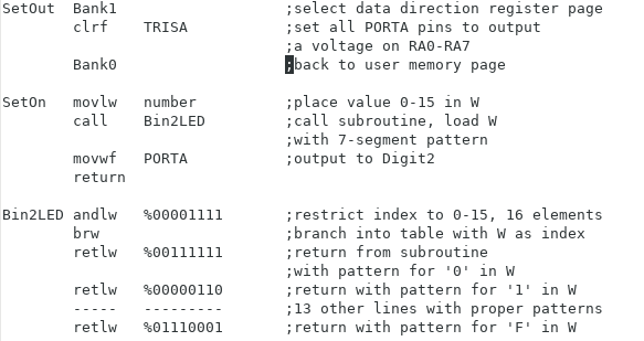
You can include a table of these patterns into a subroutine. By placing a number 0-15 into W and calling the subroutine, W will be loaded with the 7-segment pattern for that number.
Binary numbers are preceded with a '%' sign.
The brw instruction adds the content of W to the program counter (PC) to skip past 0 or more instructions, in this case to index into a table of values.
The retlw instruction loads W with the given constant and returns from the subroutine to execute the instruction that follows 'call Bin2LED'.
The andlw instruction clears the upper nibble of W, preventing it from indexing past the size of the table and crashing the program, in case the user enters an invalid number. For this to work, the table must then include sixteen (or more) retlw instructions.
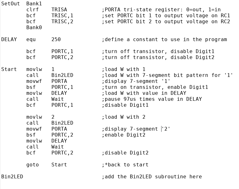
Multiplexing the two 7-segment displays
The accompanying code shows a scanning loop where two PORTC pins, RC1 and RC2, are used to control the two 7-segment displays by changing their cathode voltage. The maximum current through an RC1, RC2 pin is 20mA. Since your previously estimated cathode current did exceed this value, then 2N3904 NPN transistors can be used to provide the required current gain:- the collector is connected to the display common cathode,
- the emitter is connected to GND,
- the base to a PIC pin through a ~4700Ω resistor.
- Add the transistor circuits, as per your sketches.
- Connect the a-g,dp segments of Digit1 and Digit2.
- Execute the code. Change DELAY to adjust the scanning rate. When do the two displays appear simultaneously on?
A two-digit seconds timer
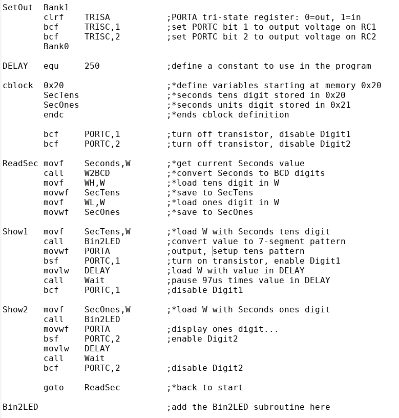
There are several predefined PIC data memory locations (file registers) that are used to pass parameters between the user program and PIC subroutines. For example,Seconds is an 8-bit register that contains a value Seconds[7:0]=0-59, updated every second by a PIC resident real-time clock.
WH, WL are registers consisting of bits WH[7:0], WL[7:0] in data memory, typically used to store the result of a subroutine call.
The subroutine W2BCD converts the value in W to three binary coded decimal (BCD) digits, the hundreds value (0-2) in WH bits 4 to 7, WH[7:4], tens (0-9) in WH[3:0] and ones (0-9) in WL[3:0]. In converting Seconds, WH[7:4]=0, WH[3:0]=tens, WL[7:4]=0, WL[3:0]=ones.
Edit your multiplex code as shown. Note the '*' tagged instructions. Your dual display should increment each second, then at 59 advance to 0. What instruction would you add at the start of the program to reset Seconds so that the count begins at zero?
Comment out the call Bin2LED instructions. What is displayed?