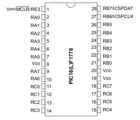
The PIC1778 microcontroller
The PIC1778 pin-out shown outlines the names of the PIC input-output port pins. Each of these pins
can also function as external connections to the various analog and digital functions that are
available on the PIC, with the exception of the
The PIC pin RE3 will be used as a 'Reset' input that restarts the PIC program when
connected to GND. The RC0 pin is used as a digital output connected to an LED.
Executing an instruction that changes the logic level at this pin will turn the LED on or off.
This pin will be used as a visual indicator and as a source of a digital signal that can be
monitored with the scope.
Pins RC6, RC7, RB4 and RB5 interface to a USB module that will be used to connect the PIC to a PC
and allow the PIC to be programmed with the picl1778
IDE (integrated development environment) software.
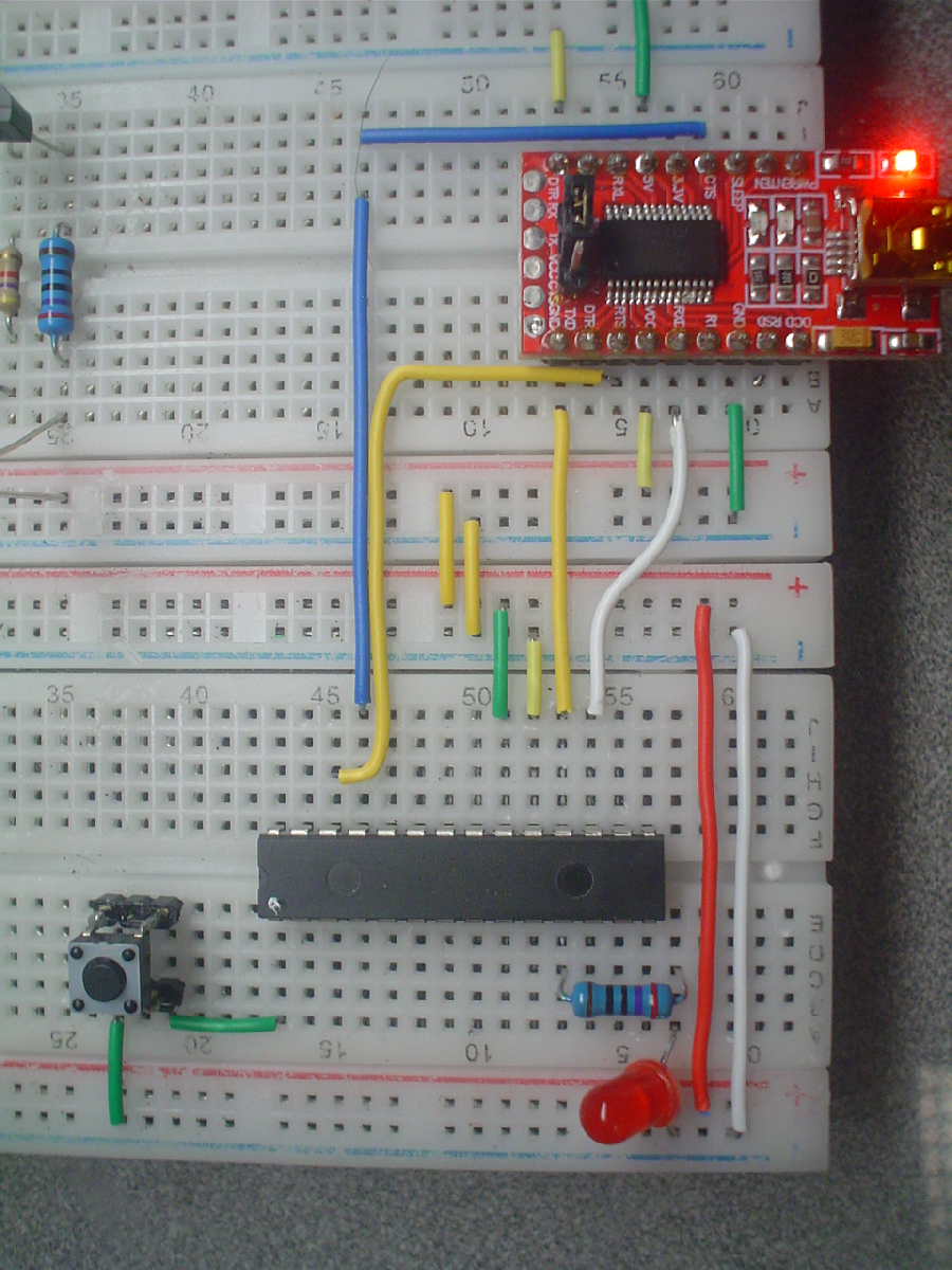
Adding the USB module and PIC circuits
Let us begin by adding the PIC circuit components. The USB module will be used to supply power to the breadboards. Install all components and rigid jumper wires exactly as shown.- Remove the current power module from your breadboard.
- Insert the USB module in it's place, exactly as shown.
- Connect the 5V and Vcc pins to the red 5V power rail.
- Connect the two GND pins to the blue 0V ground rail.
- Connect the USB module to a computer USB port.
- Disconnect the USB module from the computer.
- Insert the PIC16F1778 chip, as shown with pin 1 to the left.
- Connect the PIC pins Vss(8,19) to 0V, Vdd(20) to 5V.
- Propagate power to the bottom breadboard, as shown.
- Add the 270 Ω resistor to RC0(11) and the LED to GND.
- Add the pushbutton 'Reset' switch between RE3(1) and GND.
- Connect the PIC to the USB module:
RC6(17) to RXD, RC7(18) to TXD, RB4(25) to CTS and RB5(26) to RTS. See diagram in next slide.
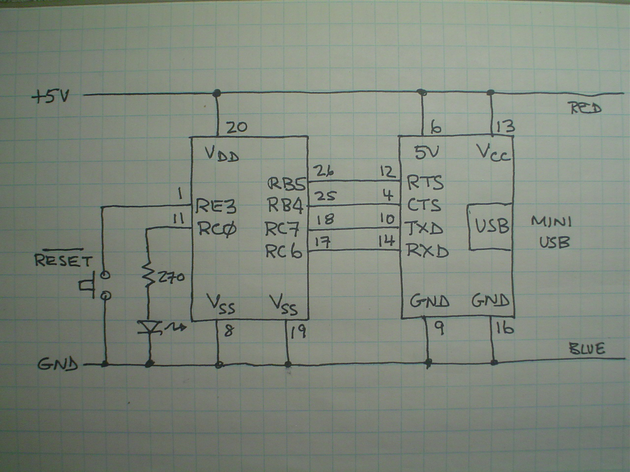
PIC connection to the programming software
Before applying power to the USB module, verify that your circuit connections match those shown in the circuit schematic, then have the TA review your circuit. If all is well, reconnect the USB module. The PIC LED should light for around one second, then turn off. Press the Reset button; the LED should light and turn off as before. You now have a working PIC circuit.
With the PIC resetting as expected, the next step is to verify the USB connection.
- From a terminal, type 'picl1778' to start the IDE software.
- Press the Connect button on the left. The icon should change and a Connected to PICLab message appear at bottom of the program entry window.
- Click Options, then Reset PIC. The PIC LED should light as when you pressed the 'Reset' button.
Some basic PIC programming exercises
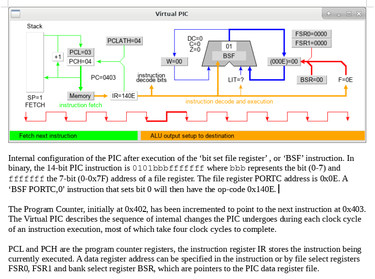
Click File, New to clear the program entry window., then enter:
bsf PORTC,0 ;set the PORTC bit.0 pin RC0 to ~5VClick Build to load and run the instruction. The LED connected to RC0 should turn on and stay on. Change bsf to bcf and click Build to turn off the LED.
The following PIC code sets up a loop that turns the LED on and off. Edit the previous code as follows and monitor RC0 with the scope.
start	bsf     PORTC,0         ;set PORTC bit.0, pin RC0 outputs ~5V
	bcf     PORTC,0         ;clear PORTC bit.0, pin RC0 outputs ~0V
	goto    start           ;repeat until 'Reset' button is pressed
- The LED appears to be steadily on. Use the scope to measure the on/off times of the PIC driven LED cycle.
- Swap the bsf and bcf codes. How does the timing change?
- What are the execution times of bcf, bcf and goto instructions?
- What values of R4,R5,C might be used in the mystery circuit timing equation to duplicate this on/off cycle?
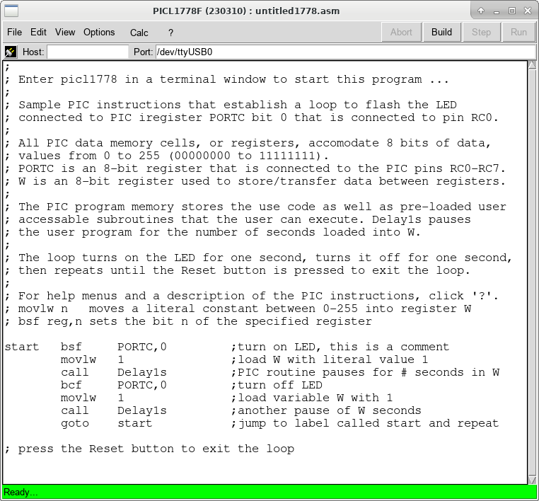
Some basic PIC programming exercises
Click File, New, then enter the code as shown. You need not enter all the comments, but do include those describing the instructions.
- Vary the loop timing by changing the values loaded into W.
- What is the longest possible LED on/off time?
- Replace Delay1s with Wait and adjust the on/off timing to turn on the LED for 20ms and off for 10ms. Verify the timing with the scope.