Opamp open-loop operation
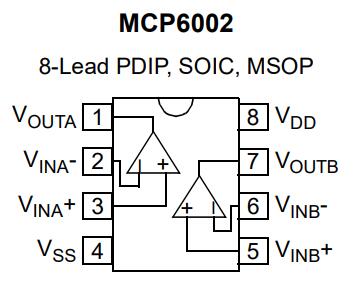
The MCP6002 8-pin chip IC1 is revealed to be a dual op-amp. You can now add the two op-amps to your schematic diagram.
Previously, you observed how the IC1 pin.1 and pin.7 voltages were related to the capacitor voltage. With the op-amps performing the role of voltage comparators, explain in detail how the voltage levels at the V+ and V- op-amp inputs result in the observed outputs at the corresponding Vout pins.
Setup your working mystery circuit, with C=0.01µF.
- Which components are connected to the inputs A+ and A-?
- Which components are connected to the inputs B+ and B-?
- Which inputs are the comparator reference voltages?
- What are the measured reference voltage values?
- What determines when the op-amps change output state?
- Describe the waveform you observe at the output pins.
- Explain this variation in Vout relative to changes in the voltages at the corresponding in V+ and V- pins.
Op-amp closed-loop operation
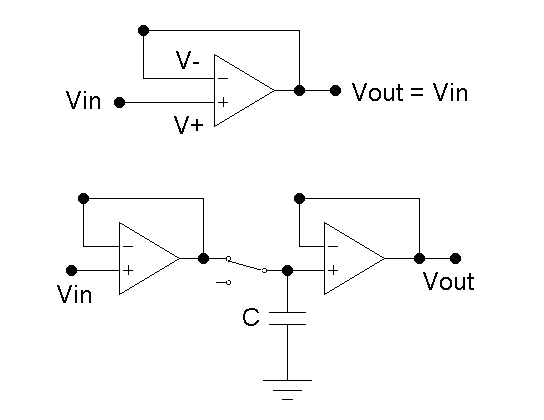
Application of feedback from Vout to V- causes V+ to track V-. The simplest arrangement, a direct connection from Vo to V-, is the voltage follower or unity gain amplifier.- What is being amplified? Derive the gain equation.
- Use an MCP6002 to assemble the memory cell, with C=10μF. Label your circuit schematic with the correct pin numbers.
- Verify the MCP6002 power connections: Vdd=+5V and Vss=0V.
- For Vin, use a 1Hz, 5Vpp sine wave with a 2.5V offset so that it fits between +0V and +5V.
- Record Vin and Vout as the switch is toggled. What voltage does Vout represent, with the switch open/closed?
- Open the switch and note how quickly Vout=VC decreases.
- Which op-amp characteristics are desirable in this circuit? Is the MCP6002 a good op-amp?
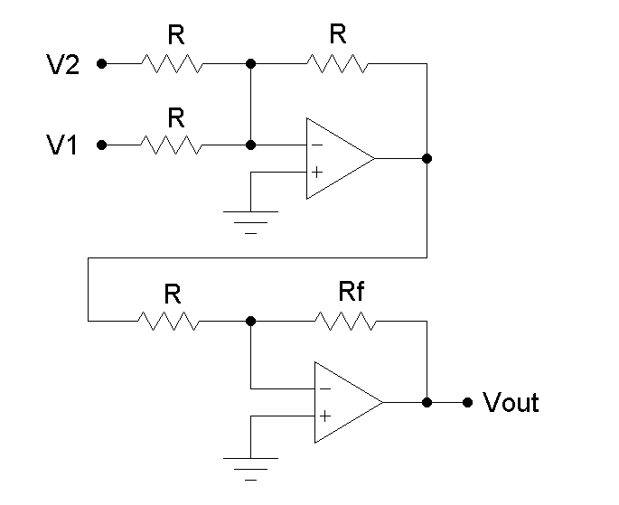
Op-amp arithmetic
An op-amp can be used to apply a linear scaling of an input voltage to obtain a desired output value. The figure shows a two op-amp circuit that can be used to evaluate the equation
The first op-amp adds an offset V2 = B / M to an input voltage V1. The second op-amp sets the gain, or slope M = -RF / R.
- Derive the transfer function for each of the op-amps.
- Combine the results to yield the scaling equation.
However, there is an equivalent circuit that avoids the voltage inversion and operates from a single +5V supply.
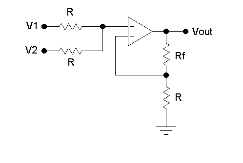
The single op-amp circuit shown has the linear tranfer function:
Suppose that a sensor outputs a voltage V1 representing some quantity that needs to be linearly scaled to another voltage, such that when V1=0.0V, Vout = 1.374V and when V1 = 5.0V, Vout = 4.126V.
- Derive the circuit transfer function, assuming an ideal op-amp. What is the slope M? and the y-intercept B?
- Manually determine values for V2 and Rf, with R = 100kΩ.
- Construct this circuit using the MCP6002 op-amp, with power connections Vdd=+5V and Vss=0V.
- How did you set up the voltage V2? Explain.
- Set V1 to GND and measure Vout to verify that the output is as expected. Repeat the test with V1=5V.
- Set up several other voltages for V1 and record Vout.
- Tabulate and plot the data, then fit it to a straight line to get the slope and y-intercept. Compare these with M and B.